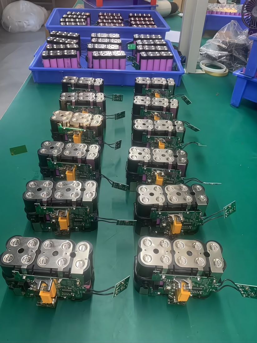
When a custom pack fails at incoming inspection, the cause is often not the cells or the BMS — it is the interface. A connector that looks right but has reversed polarity, a pinout that matches the plug but not the signal order, or a lead too thin for the continuous current can stop a product at the last step. None of these are dramatic engineering problems; all of them are avoidable with a clear interface brief.
1. Start with the mating part, not the connector catalogue
The most useful starting point is the connector on the device side. Send a photo of the mating socket with a ruler beside it, the part number if you have it, and a note on which way the latch faces. From that, a factory can confirm the family, the pin count, the pitch and the orientation. Choosing a connector from a catalogue first and hoping it matches the device is the order that produces mismatches.
2. Know the common connector families
Most custom packs use one of a handful of interface types. The table below is a general orientation, not a specification — current ratings, pin counts and wire gauges are always confirmed against the actual part and your load.
| Family | Typical application | Key point | What to confirm |
|---|---|---|---|
| Bullet / banana plugs | Power tools, e-bikes, older packs | Polarity by diameter or shroud | Diameter, male/female, wire gauge |
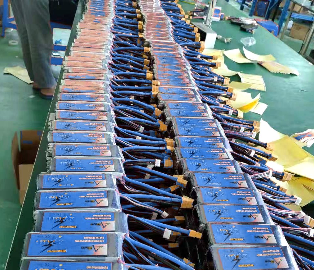
| XT-style (XT30 / XT60 / XT90) | Drone, RC, high-current compact packs | Keyed housing, polarity marked | Series, continuous current, gauge |
| JST / Molex-style board connectors | BMS balance leads, signal and low-current outputs | Small pitch, pin order matters | Pin count, pitch, pin mapping |
| Anderson-style power connectors | Storage, industrial, detachable packs | Keyed, genderless in some series | Series, current, crimp vs solder |
| Custom overmoulded lead with bare ends | Devices with their own terminal block | No mating connector to align | Lead length, strip length, tinning |
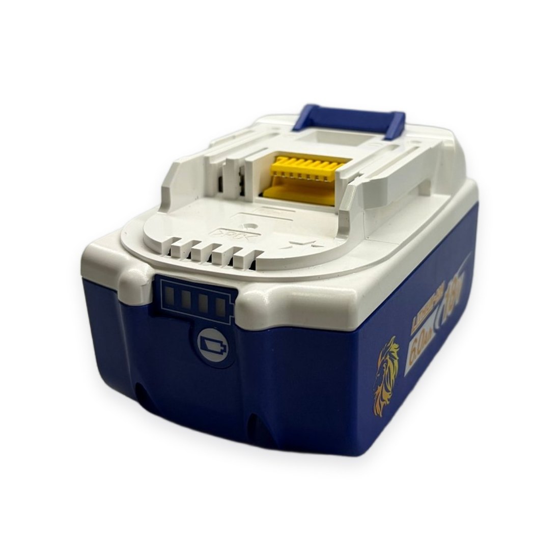
All ratings in the table are typical / on request; we confirm the exact part and current capability against your device and load before quoting. Where a pack replaces an existing product — for example a Compatible with Makita 18V LXT or Replacement for DeWalt 20V MAX interface — the mating geometry matters more than the brand name on the old pack.
3. Pinouts: matching signals, not just shapes
A plug that clicks into place can still be wrong. Balance leads, communication lines (SMBus, CAN, UART) and thermistor outputs depend on pin order. A connector with five positions can carry five different signal assignments, and swapping two of them may disable communication or, worse, put pack voltage onto a signal pin. Always send a pin-by-pin table — position number, wire colour and signal name — plus a photo of the device-side socket. If a datasheet exists, include it; if not, a clear photo with the pins numbered by hand works.
4. Current, wire gauge and voltage drop
The connector and its leads must carry the real continuous and peak current, not the average. Undersized wire heats up, and a heated connector raises resistance, which creates more heat — a loop that ends in a melted housing. State your continuous current, peak current and peak duration, and let the factory propose the wire gauge and connector series. For high-rate drone or tool packs, we match the output path to the same standard as the cells. We only build with original-pack Grade A cells — never B-grade, never C-grade, ever.
5. Keying, polarity and the "it fits" trap
Two connectors from the same family can look identical while being keyed differently, and some older packs use the same shell with reversed polarity. Keying exists precisely to prevent reverse insertion, so never cut a key or force a housing. Specify the polarity marking you expect (+ and − on the housing or the lead), and ask for a sample with the connector fitted before tooling. A five-minute check on a sample is cheaper than a batch of returns.
6. What to send us to get the interface right
Put these five things in one email: a photo of the mating connector with a ruler, the part number if known, a pin-by-pin mapping with wire colours, the continuous and peak current, and the lead length and any strain-relief requirement. With that, we can return a connector proposal and a priced pack specification. If you are replacing an existing pack, a photo of the old unit — connector side included — is enough to start.
Need a pack with the right connector and pinout?
Send the mating-part photo and your pin mapping — even a rough sketch is enough to start — and we reply within 24 hours with a connector proposal, wire gauge and pricing tiers. Samples are charged and credited to your first production order.
Quick Inquiry
Not sure which connector your device uses? That is normal. A good factory will confirm the interface from a photo before it quotes, and will flag any pinout that looks unusual. The goal is a pack that drops into your product on the first assembly — not one that needs an adapter.
Related
Browse the product lines we build — each links to its own page: